
MHA Research Heater
photos by Norbert Senf Go to Testing Data Oct 31/15: Heater build Dec 20/15: Modification 01 (firebox) Feb 15/16: Modifications 02 Jan 14/17: Instrumentation Jan 19/18: Modifications 03 (chimney) Jan 29/18: Modifications 04 (heat exchanger) 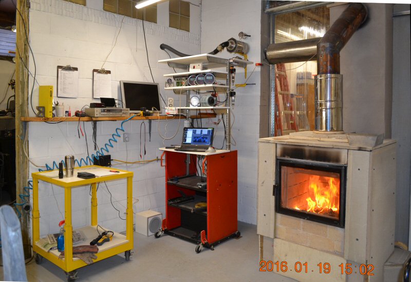 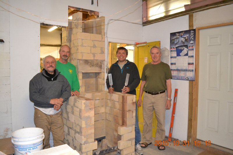 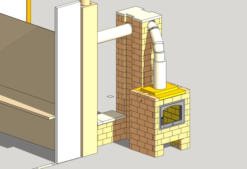 Research heater designed by MHA technical committee. The goal is to allow the EPA certification of one-off handbuilt heaters. This heater is designed to generate data to calibrate simulation software written by committee member Damien Lehmann (France). Project background and timeline, from July 2014. 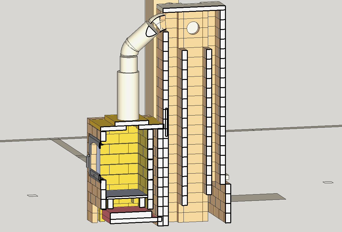 Heater section. An Austrian Eco-firebox is connected via pipe to a heat exchange section. The firebox and heat exchanger are separated, to allow for easier modification. The heat exchange section has three vertical channels of varying cross section, feeding a heated bench. The channels can be easily reconfigured between various combinations of updrafting and downdrafting. 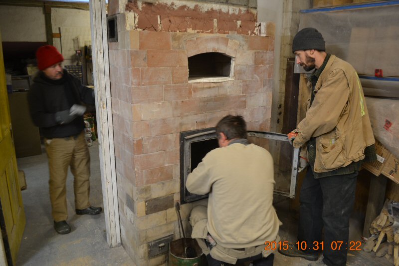 Masonry Stove Builders provided lab space at our shop in Quebec, near Ottawa. MHA held a workshop on Oct 31/15 to build the heater core. 5 MHA members attended. In the photo above, Tom Marcantonio, Alex Chernov, and Darrel Delisle are starting the teardown of the existing shop heater, a 3 year old new-model Heatkit. 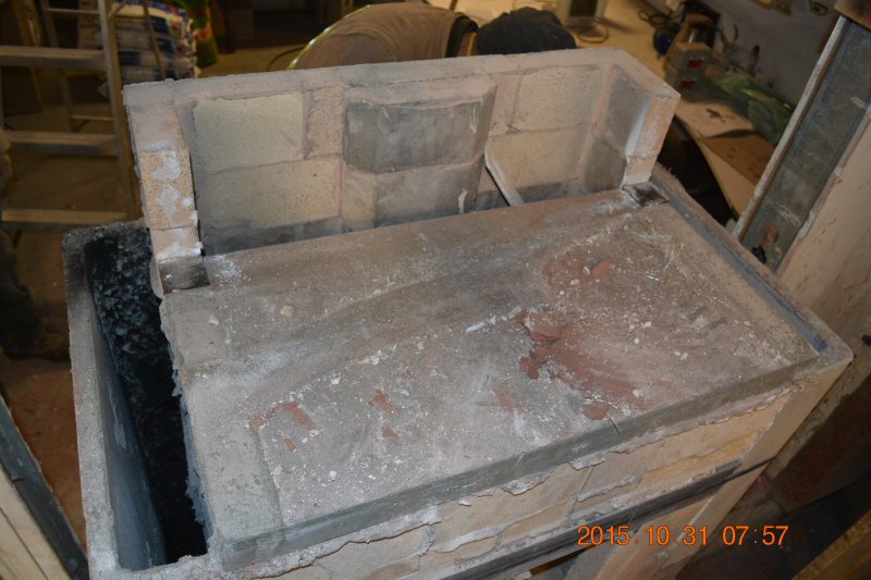 This shows a new experimental 31.5" bakeoven floor slab, using a custom castable, that underwent destructive testing in the old heater. 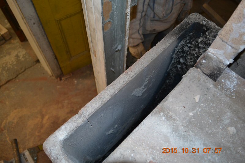 Note that all of the soot in the precast downdraft channels has burned off, except in the rear corner. 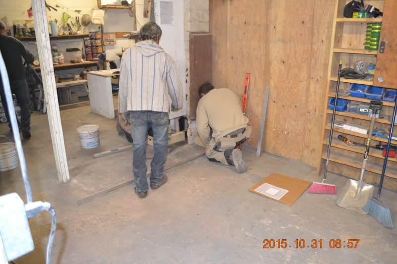 Laying out the new heater. My neighbour Marco came down to lend a hand. 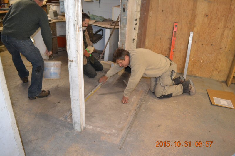 The existing masonry chimney is to the right of Alex. 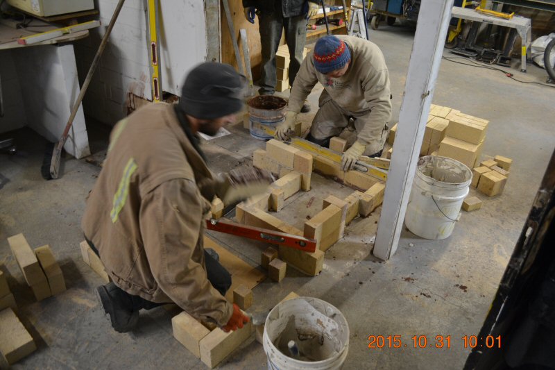 Alex lays out the heated bench while Darrel lays out the firebox. 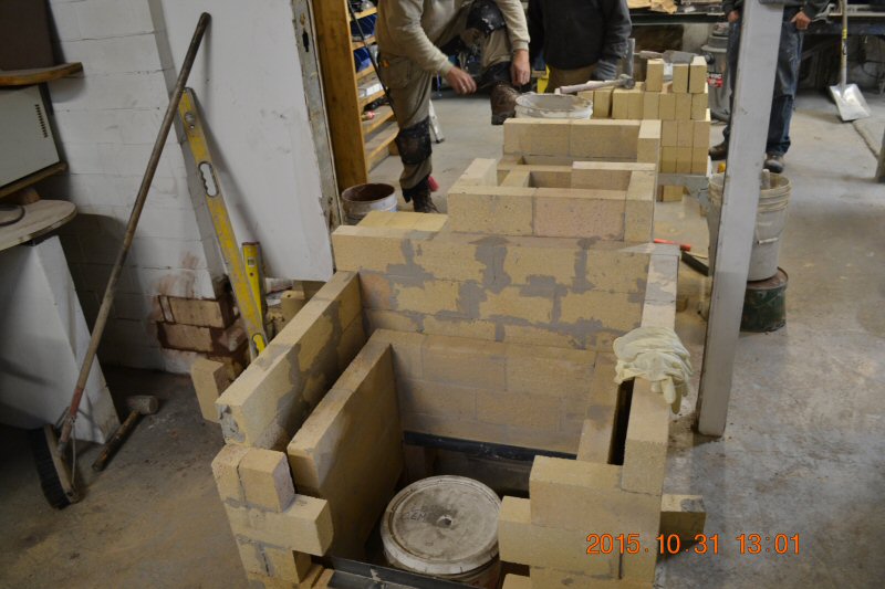 Firebox showing the air space between the firebox and facing that supplies the Ecobox horizontal combustion air slots. Heat exchanger to the rear. 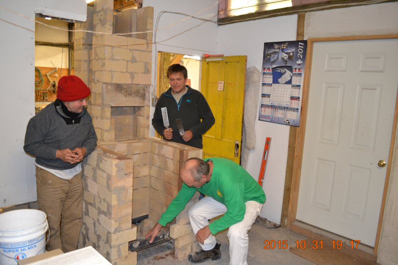 Mark Seymour works on the access opening for the scale we will install later to measure the real time burn rate. The firebox floor will float and sit on the scale. Note the horizontal air slots in the firebox. 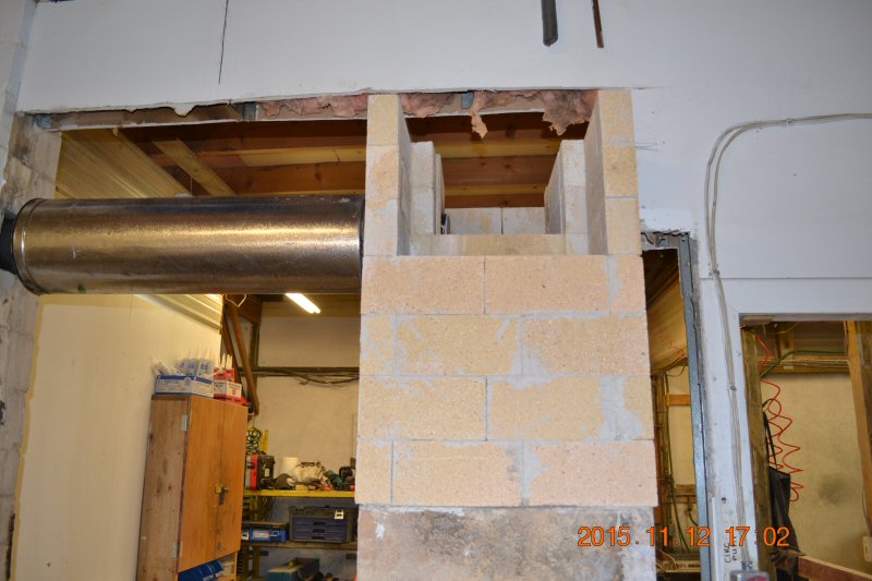 A bypass will allow additional channel configurations to be tested. We got all of the firebrick work on the core done in a day. 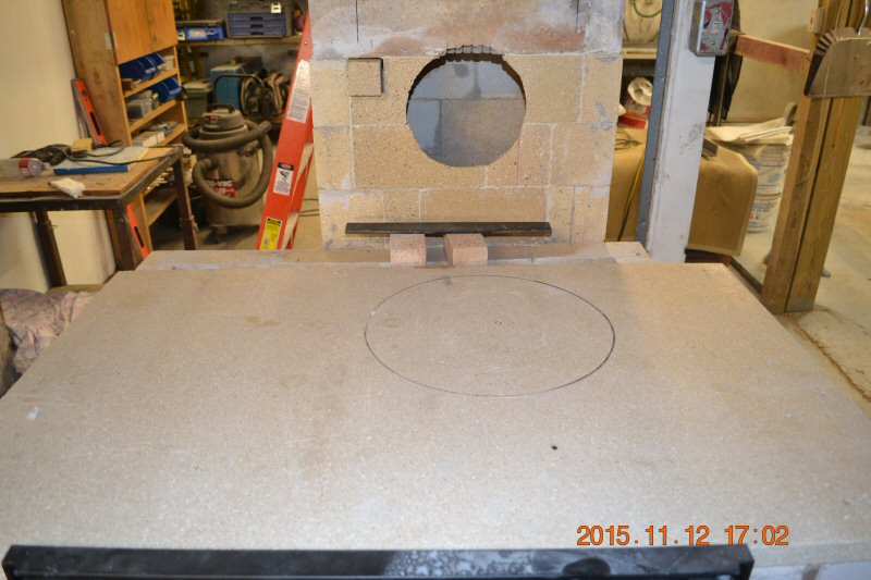 An additional connection halfway down the first channel, to allow for additional configurations. Vermiculite board forms the ceiling of the firebox. 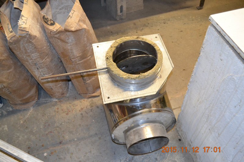 ICC anchor plate with damper will block off the lower connection. 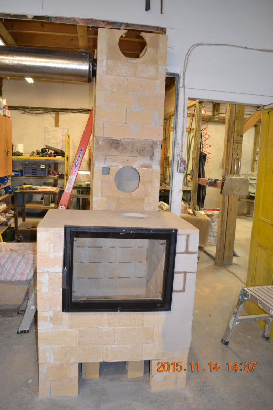 Pisla 602 22" door installed. 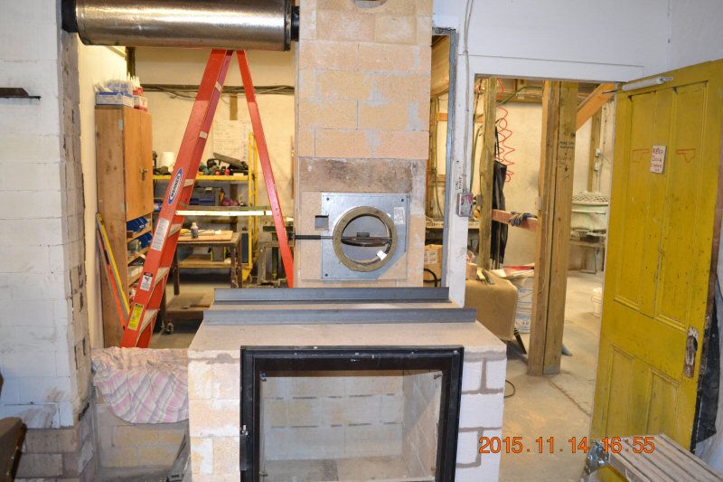 Angle irons to take the weight of the chimney off the vermiculite board. 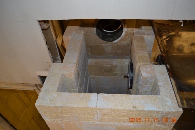 View from top, showing the bypass flue blocked off with a plug. 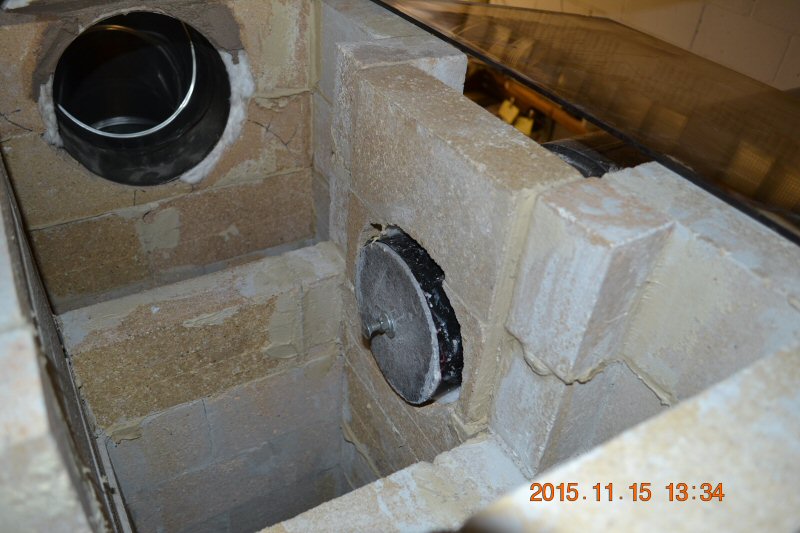 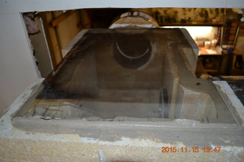 The ceiling is formed from a plate of Robax ceramic glass on a clay bed. 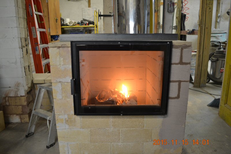 First fire. We used Selkirk 8" chimney to connect the firebox to the heat exchanger. 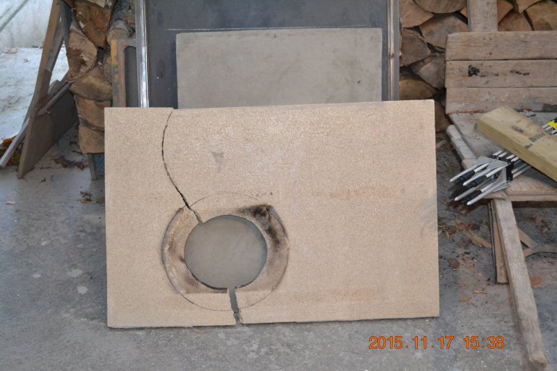 The vermiculite board did not like being used this way. 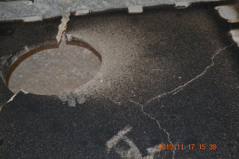 Many cracks. Back to the drawing board. It would be interesting to know whether a free-floating piece would do this, if it did not have the weight of about 75 lbs of chimney pushing on the angle irons, pehaps pinning it in place in an expanded condition and then causing tensile stress when cooling and contracting. 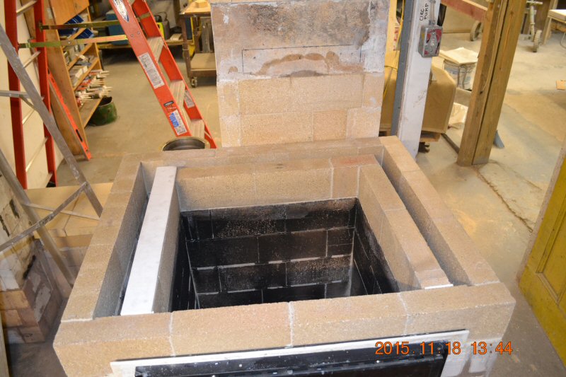 After watching the heater burn, we decided to add a course to the height of the firebox. We had wanted to see the effect of horizontal slots at the top, above the vertically stacked wood. With the 8" ceiling outlet, there is positive pressure at the top of the firebox, and smoke in fact exited through the top slots and re-entered with combustion air at the bottom slots - note that the air slots are white, except for the top slot . Hence, no slots on the extra course. 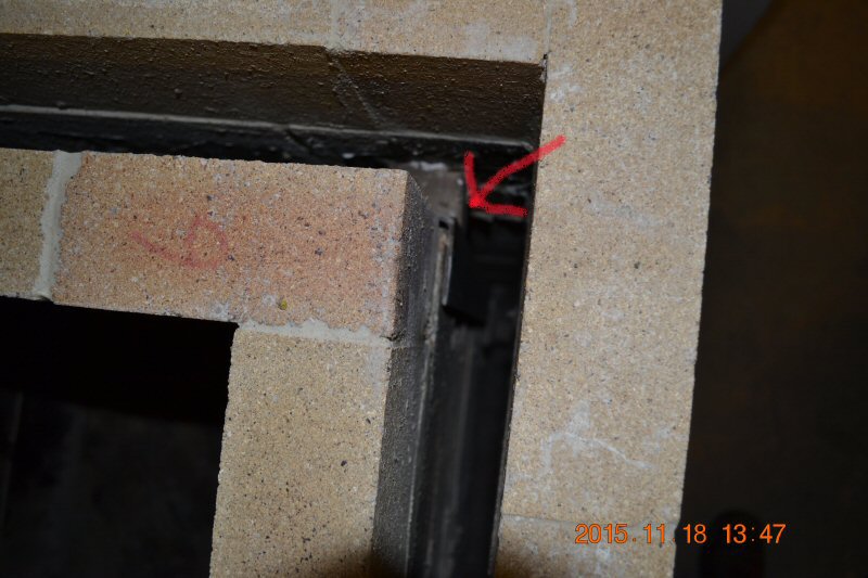 The firebox is fairly fragile, particularly since we used straight clay instead of Sairset. Just visible is a steel reinforcing harness we added between the two rear corners. 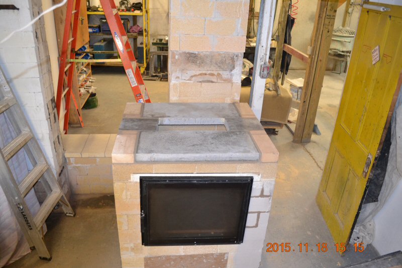 For the second iteration, we used Heatkit bake oven floor slabs to cap the firebox. The lower channel connection was abandoned and blocked off. The Selkirk chimney was abandoned. We found it unwieldy, and the T-piece was significantly out of square. 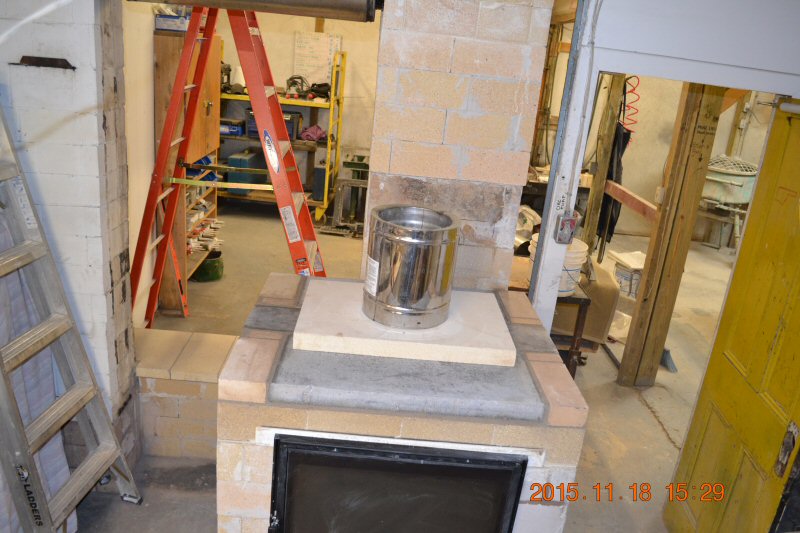 We used an Austrian 2" firebrick tile to start off a piece of ICC 8" Excel. The firebrick slab did not like it, and cracked in two right away. It would have been a lot easier to cut the hole by cutting the slab in half, first. Doh! 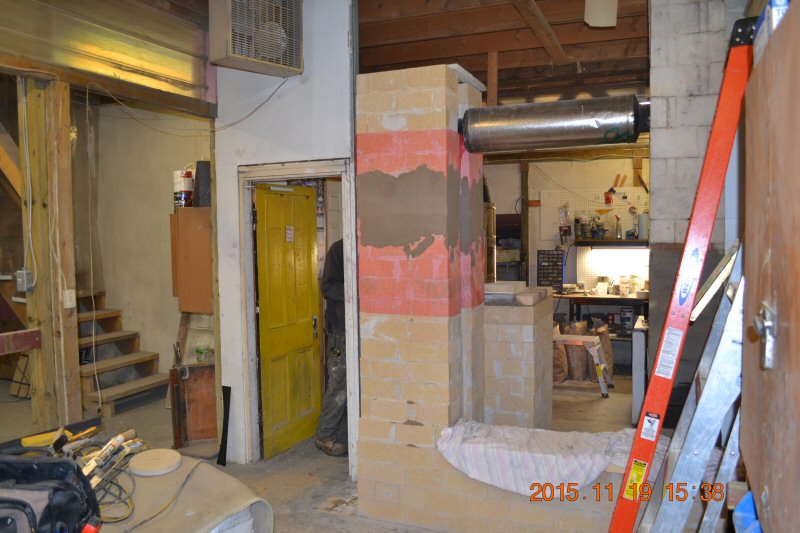 The middle channel uses stacked joints all the way up and we therefore reinforced the heat exchanger with glass mesh skimmed with clay/sand plaster. 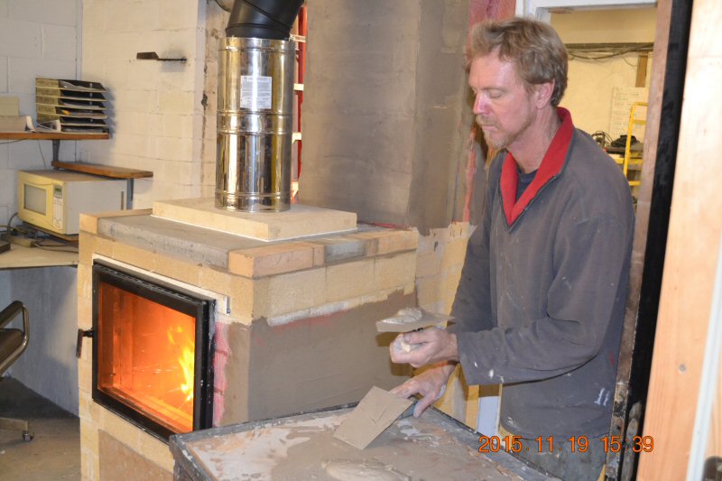 Matt Anderson plasters the firebox. The connection off the firebox is a combination of Excel chimney and black stovepipe. The connection includes an offset and we used 2 adjustable elbows. 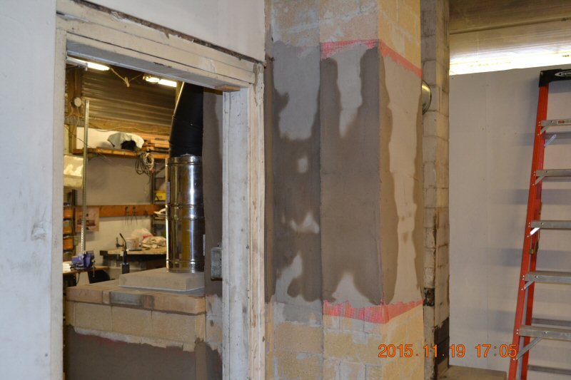 Interesting drying pattern on the plaster gives a graphical representation of the temperature distribution in the heat exchanger. The initial configuration has all three channels downdrafting in parallel.  Sketchup section showing firebox to the right and chimney at the bottom. The first and second channels have the same cross section, but different aspect ratios. The third channel has less cross section, and higher aspect ratio. 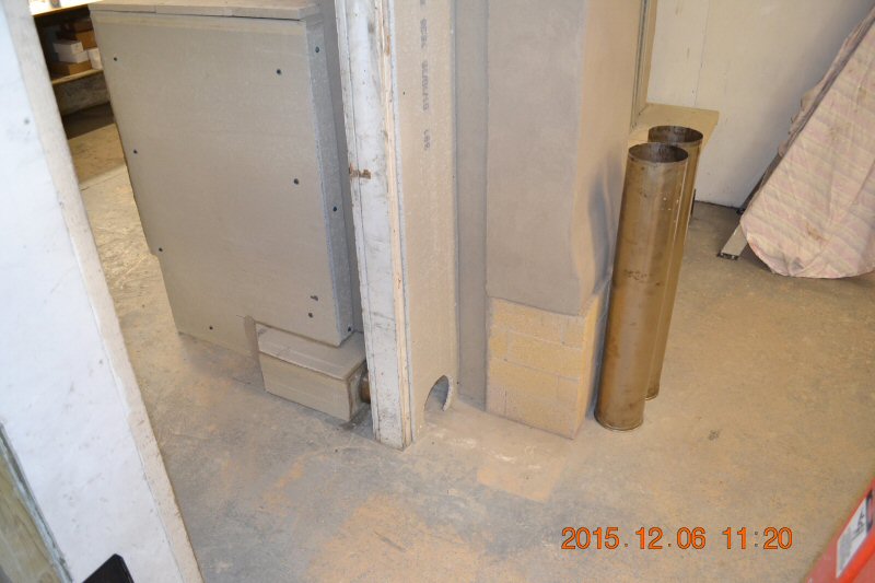 After skinning, the firebox was insulated with 1" of mineral wool board (Roxul Drainclad) and covered in cement board. At the bottom is the combustion air inlet. It will be important to measure combustion air flow precisely. You need about 6' of straight pipe in order to get smooth enough flow to allow accurate measurement with a thermo-anemometer. 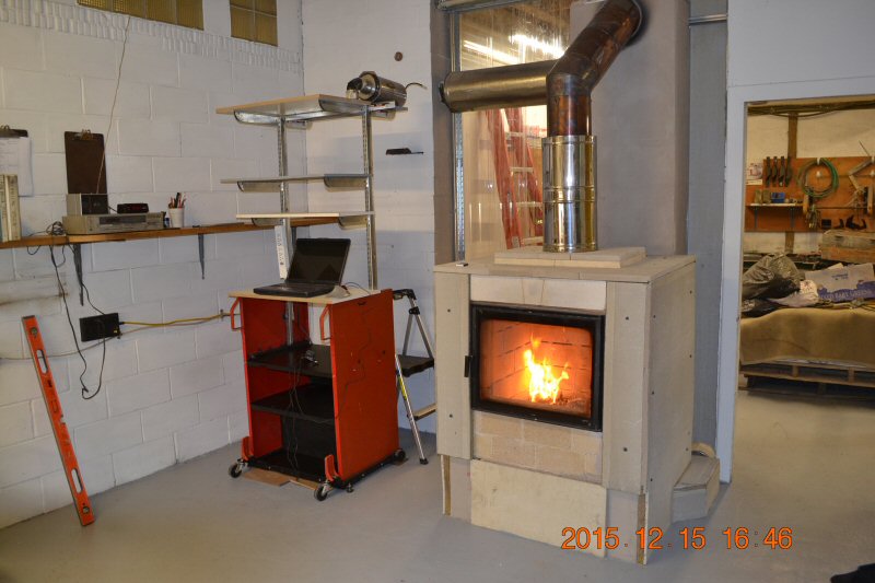 The black stove pipe has been changed out to 8" Excel stainless liner. We may decide to insulate it. The clay seal on the Robax ceiling slab proved to leak. The seal was replaced with 1/2" ceramic wool, a layer of 1" insulating millboard was added to the Robax, and it was weighted with bricks to compress the gasket. Right now (December 15) we are building an instrumentation rack to the left of the heater.  Performance so far is very impressive. With the thin single skin heat exchanger, we get fast heat in the morning. With the current mild weather, around 30F, a 60 lb load of wood will overheat the shop. A guess at the average stack temperature is around 220F - 250F. Surface temperature at the top of the channels is 270 F. It seems to burn extremely clean. With overnight heat storage in the insulated firebox, we get around 200F preheated combustion air for startup. One small horizontal hairline crack in the plaster, near the top - impressive, no doubt due to the even heat distribution from the parallel downdrafting (bell effect). 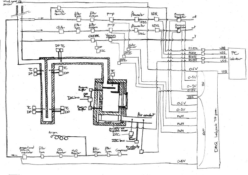 This schematic for the instrumentation and piping layout was provided by Damien Lehmann. 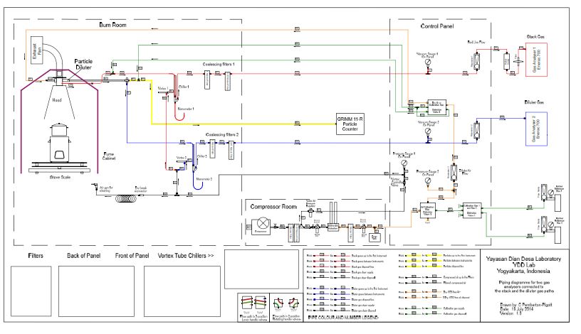 Tech committee member Crispin Pemberton-Pigott provided this piping diagram for a testing system he has helped develop that is widely used around the world for cookstove testing. We will incorporate large portions of this method. See also: December 20/15: Firebox modification February 15/16: Modifications 02 Check out other current research at Lopez Labs |
This
page was updated on December 16, 2018
This page was created on December 13, 2015