
Fireplace Retrofit
See also:
Alaska Fireplace Retrofit
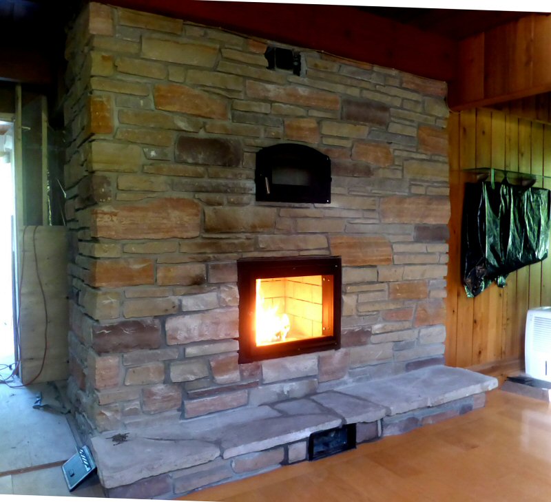
Finished masonry heater.
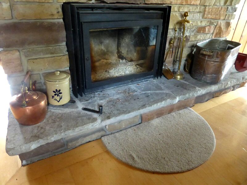
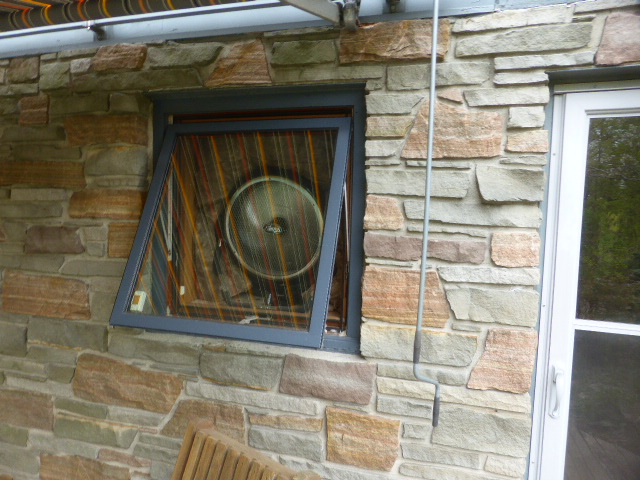
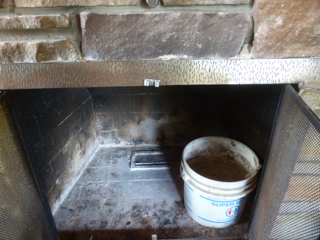
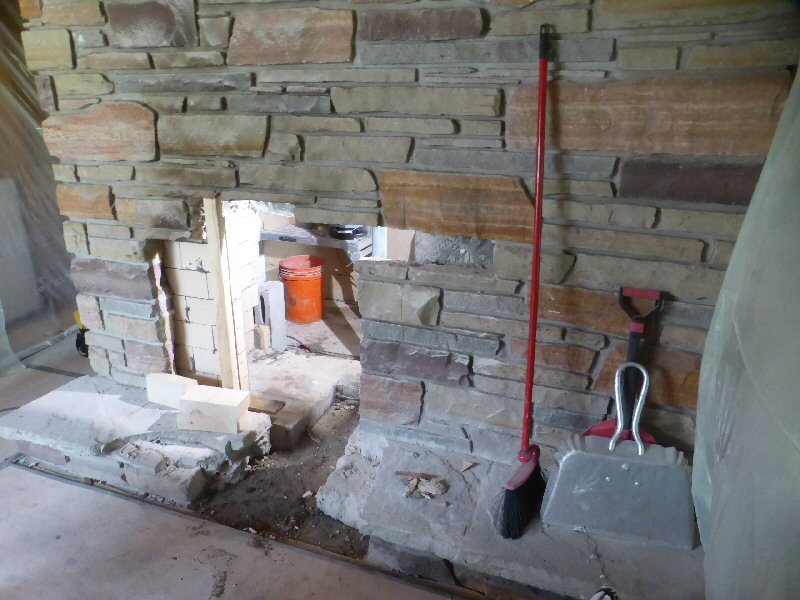
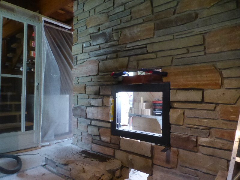
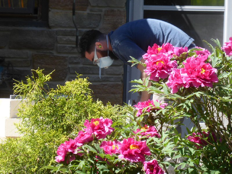
Existing sandstone lower level fireplace with fireplace insert installed.
This was the main heat source for the house, and the clients spend most of their time in the winter in this room.
Single split 1960's bungalow with walk-out lower level to the back yard.
Front door is at the top of the first stairs, just to the left.
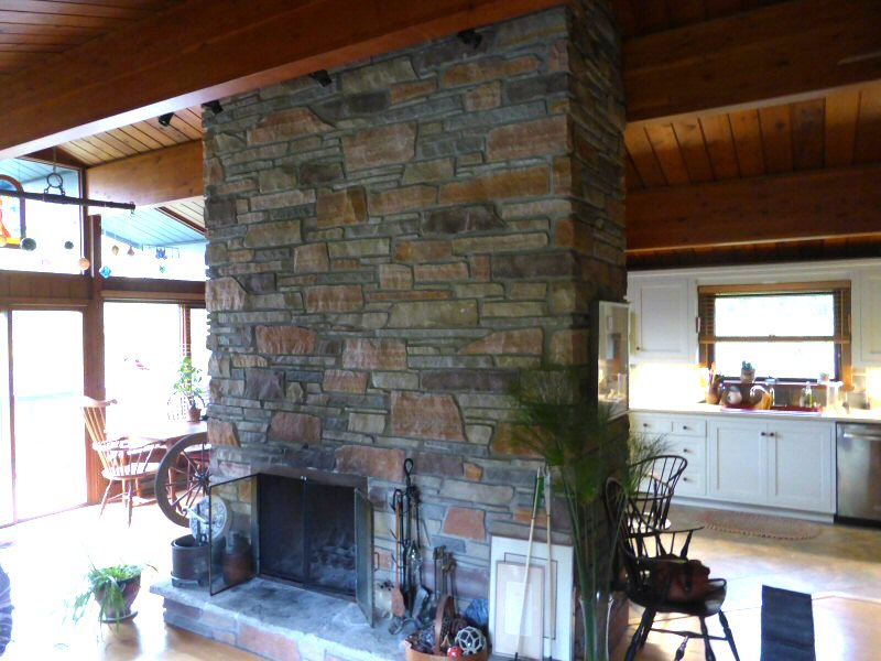
Upper level fireplace
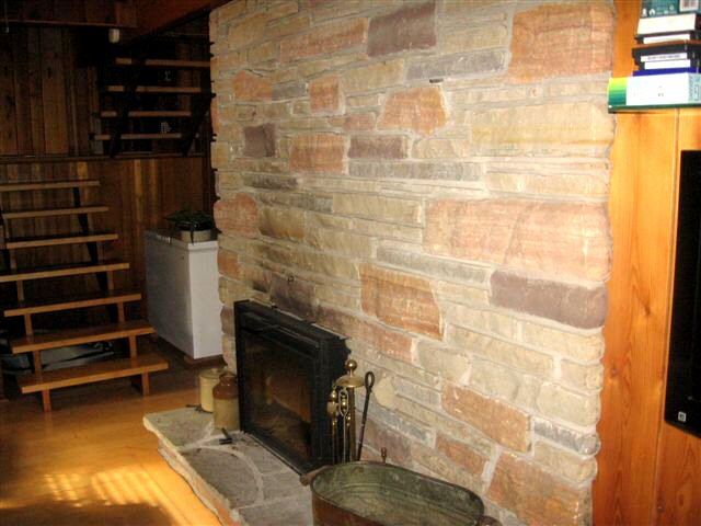
Existing fireplace layout. The lower level firebox is on the left.
Preliminary design for lower level fireplace retrofit.
A standard Heatkit core, with a custom built downdrafting heat exchange section to the left (in blue).
The left and front sides of the core will contact the original sandstone veneer.
The rear and right sides of the core will receive a sheet metal skin, and use the Austrian air gap system to transfer heat to the exterior masonry.
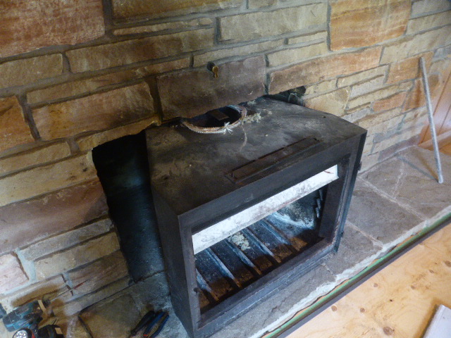
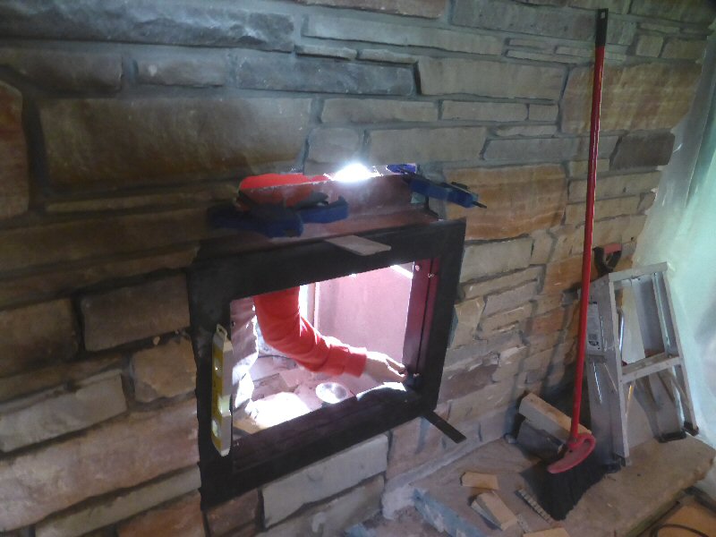
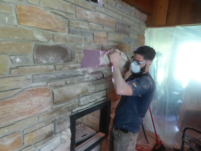
Removing the insert.
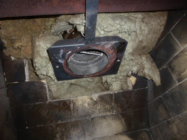
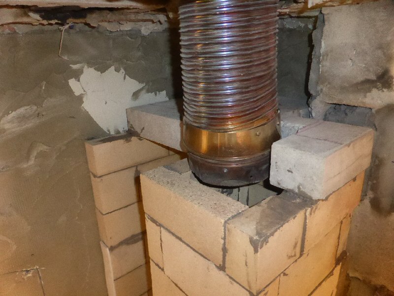
Bottom of 7" stainless liner that was installed for the insert.
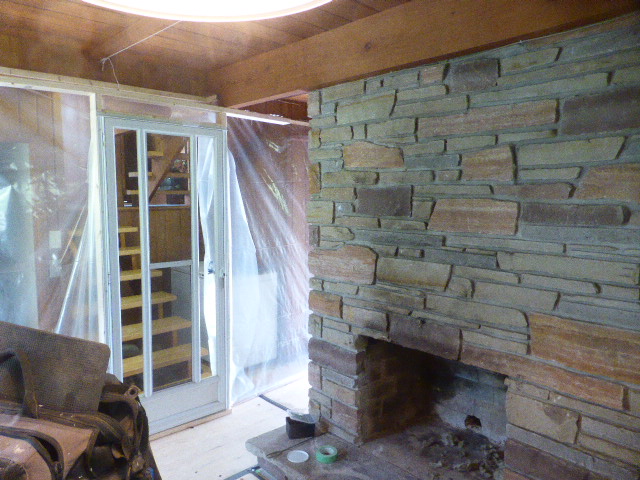
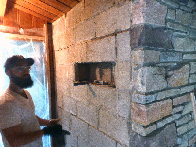
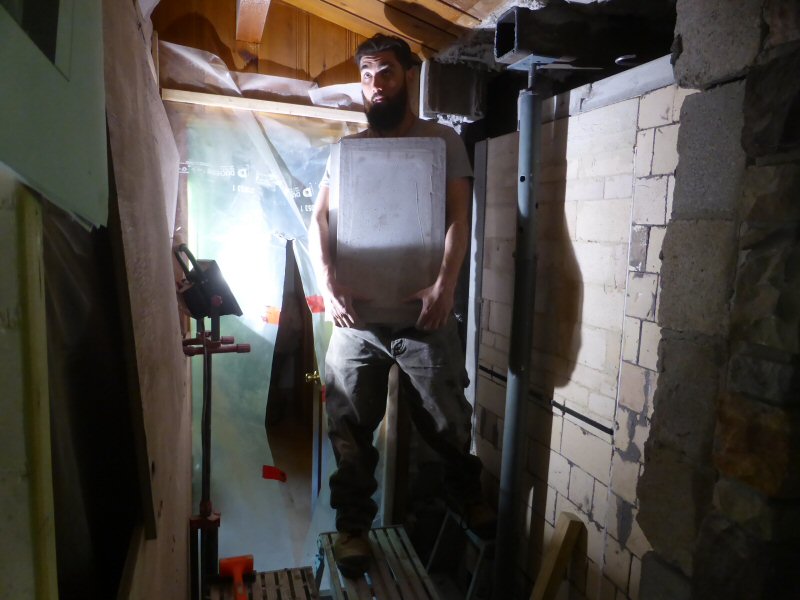
A professional crew installed the dust enclosure for the room, including the floors.
Note the screen door installed into the plastic.
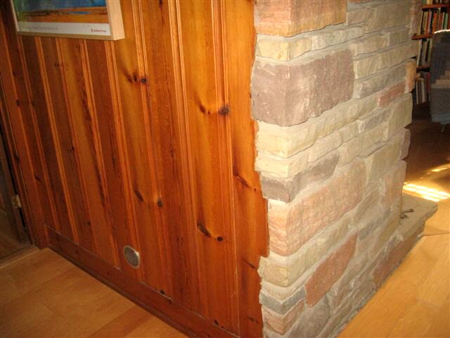
Rear of fireplace is panelled with wood.
An exhaust sytem depressurizes the room.
The clients reported zero dust in the rest of the house.
Fresh air into the room was adjustable, depending on which side of the fireplace we were
working on.
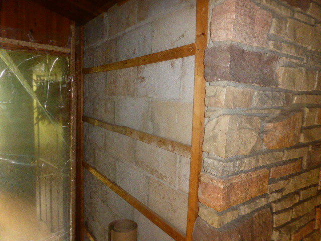
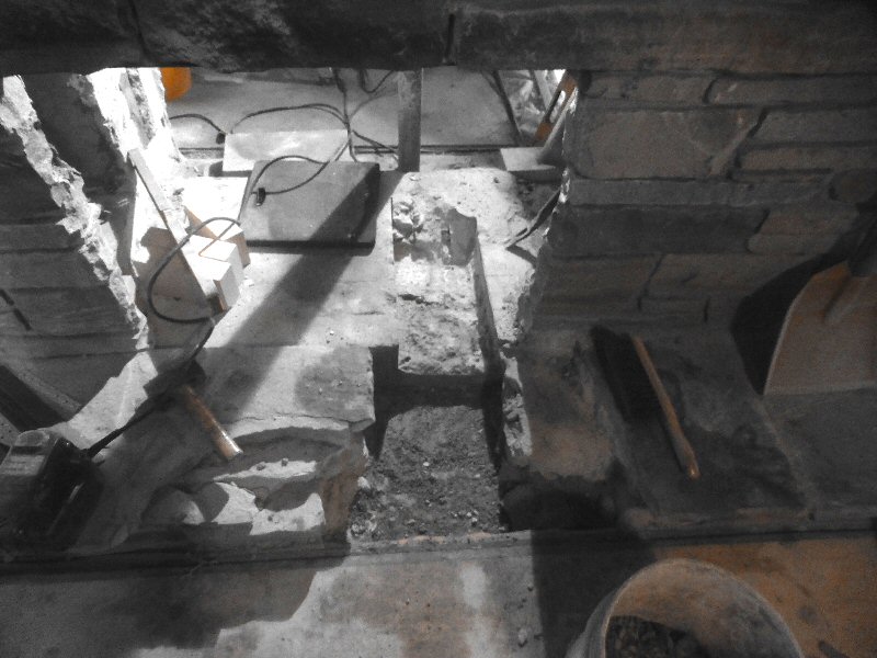
Starting to gut the fireplace from the rear.

Rear concrete block wall removed. It was a combination of 8" and 12" blocks, well bonded.
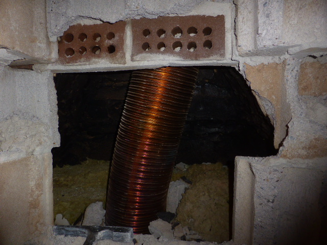
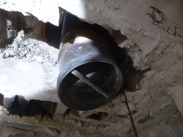
Original fireplace smoke chamber with liner running through it. Note that the cast iron throat damper has been
cut to accommodate the liner.
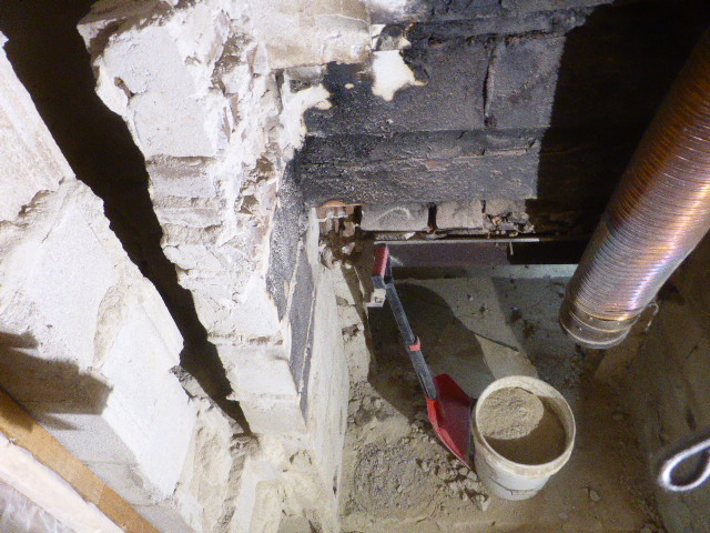
To the left is an ashpit for the upstairs fireplace.
It was completely filled and, interestingly, did not have a clean out door.
Standard cast iron fireplace pivoting ash dump on the upstairs fireplace.
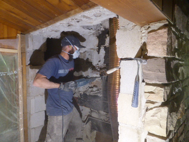
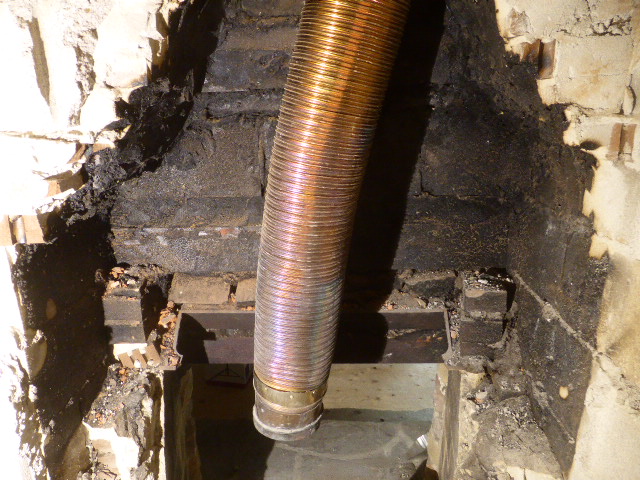
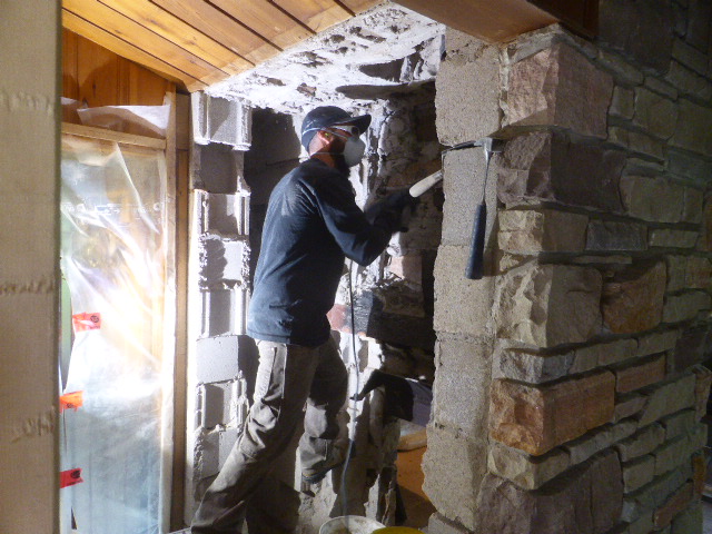
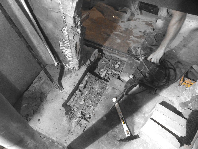
Demoing the smoke chamber using a 7.5 amp Bosch SDS-Plus hammer.
Note that the chimney liner is in the way.
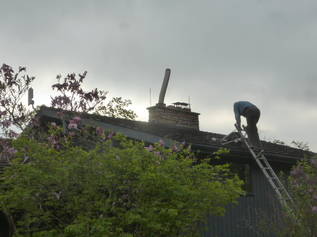
Chimney liner pulled up.
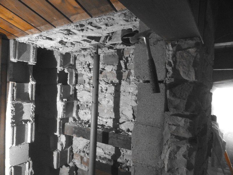
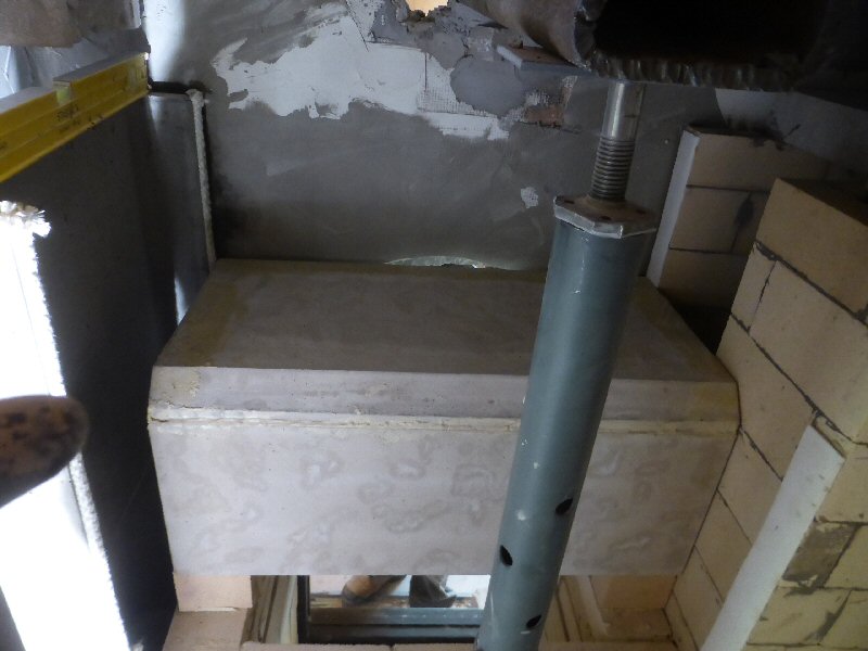
A temporary jack post is installed as a precaution.
Back of the facing stone is visible.
Raised chimney liner.
The original attachment still in place was for pulling the liner down the flue. It is a special heavy gauge
liner, and was a tight fit.
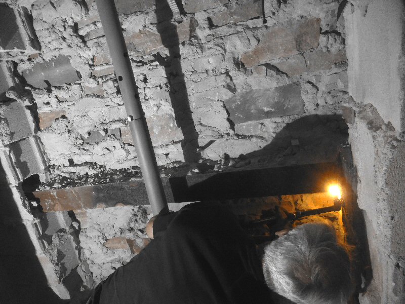
The smoke chamber sat on a full length steel lintel that was cut out.
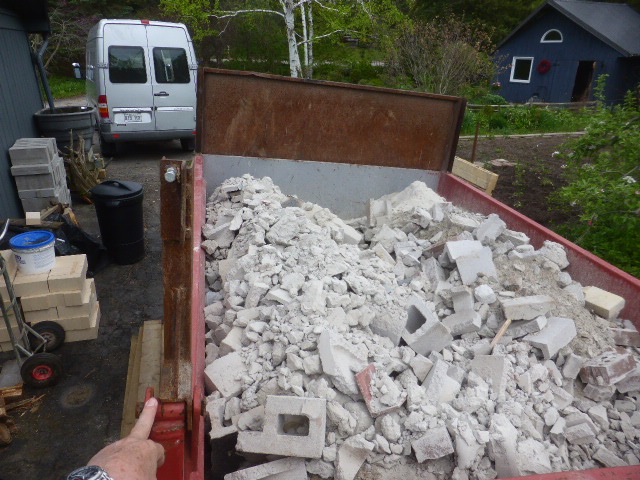
Large farm dump trailer was nearly filled with debris. It went to a nearby culvert project.
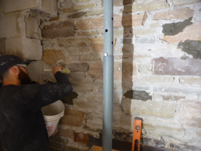
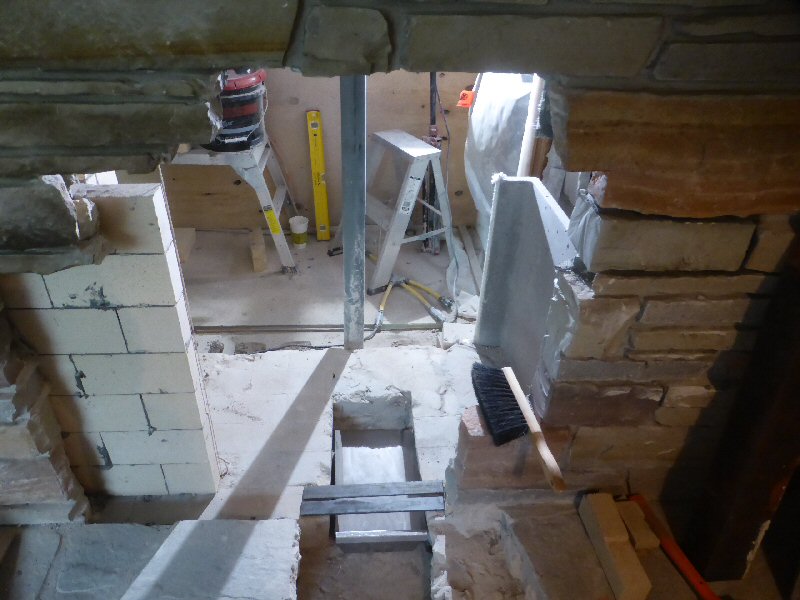
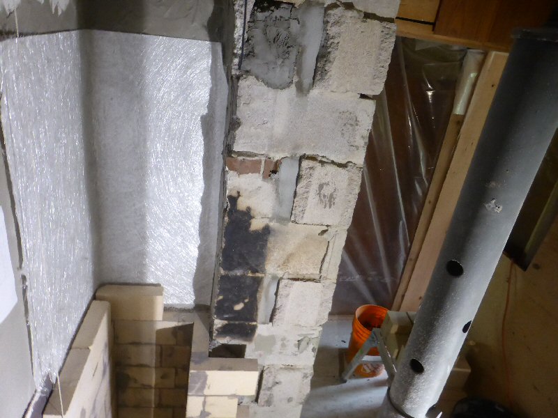
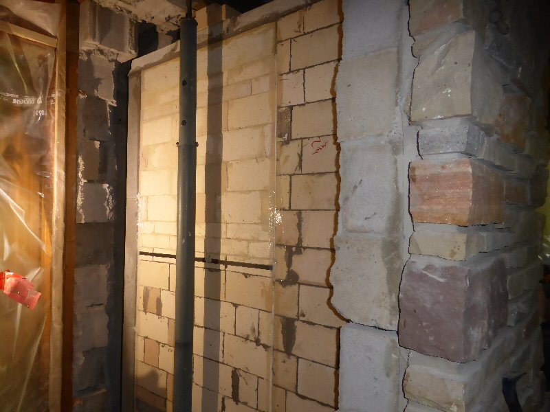
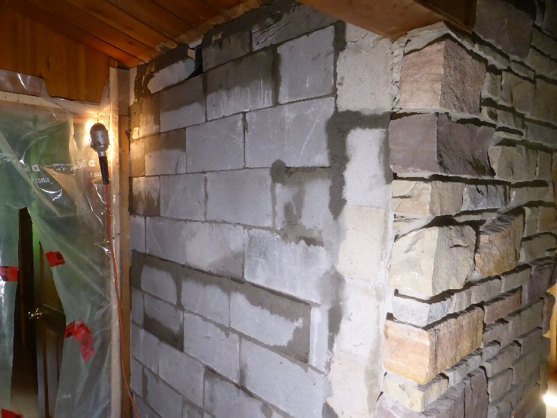
The cavity has been gutted down to the existing 4" sandstone facing.
We want to make the rear face of the stone airtight, and to come to either a plumb or slightly outward
tilting plane that we can built the core tight against, for good heat transfer. The core grows in height
about 1/8" when hot, and we don't want it lifting the facing and creating horizontal cracks.
We start by filling in the deepest pockets. To assure a good bond, they are primed first with thinset.
Filling in the depressions in several coats, fresh enough to ensure a bond.
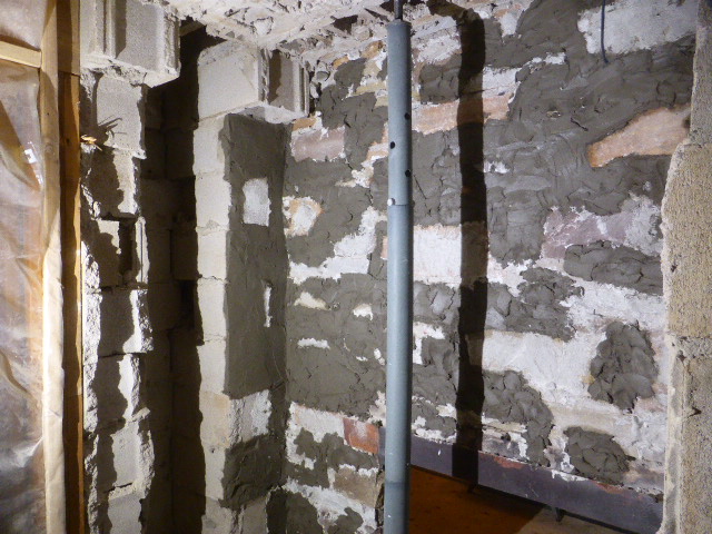
Fairly flush. A few high spots sticking out.
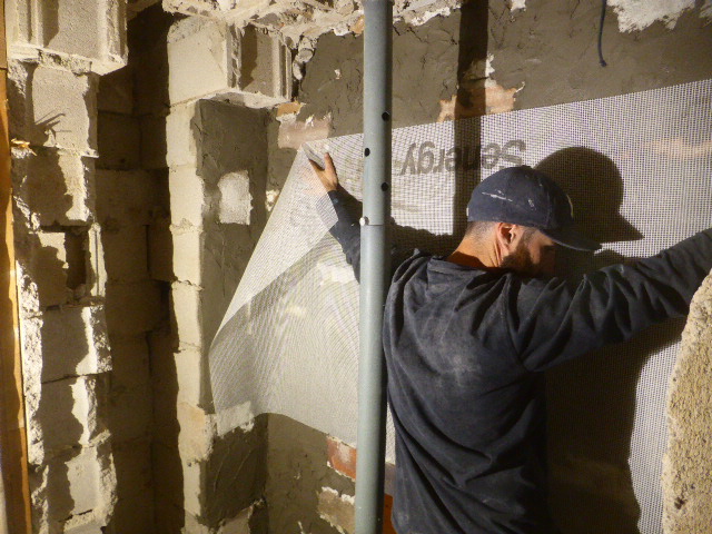
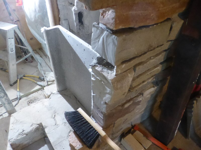
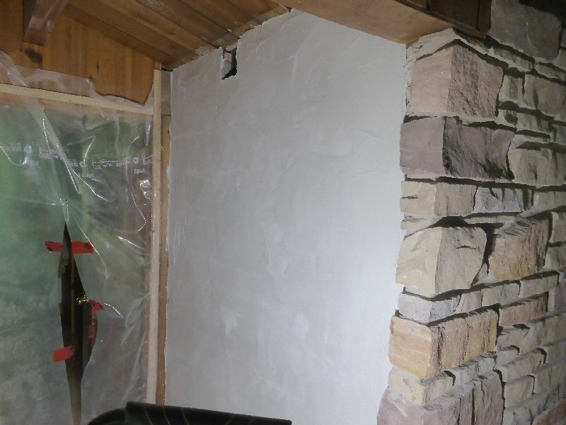
The rear is skimmed over with thinset with glass mesh embedded. This provides a strong tensile skin that
will add strength to the sandstone, give it flexural strength, and tie it in to the concrete blocks at the left.
High spots are marked in red.
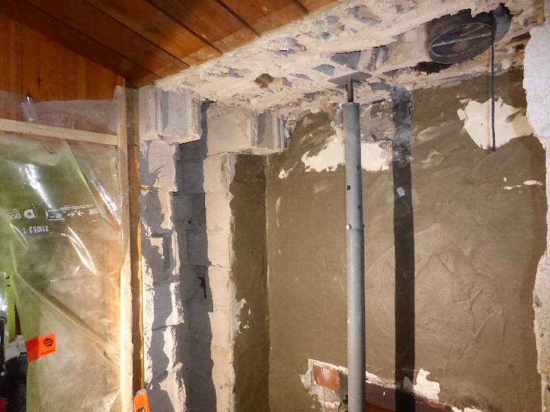
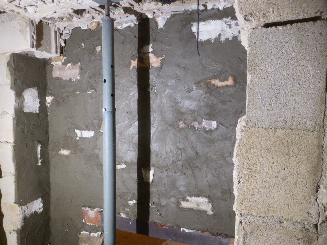
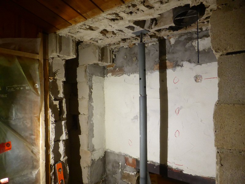
Additional coats of mesh and thinset. The contrasting thinset color allows the high spots to remain visible.
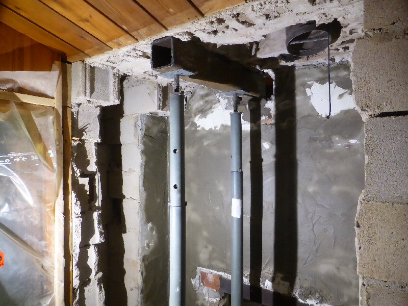
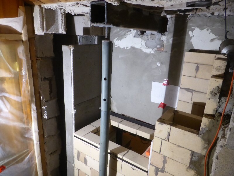
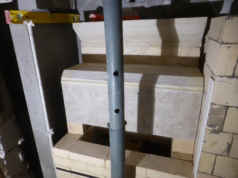
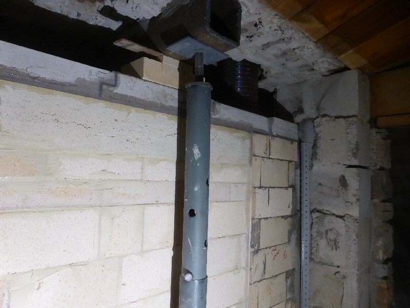
A 6"x6" steel structural support beam is added.
The jack post at the rear of the fireplace is permanent. The second jack post provides temporary support
while the support masonry in front sets up.
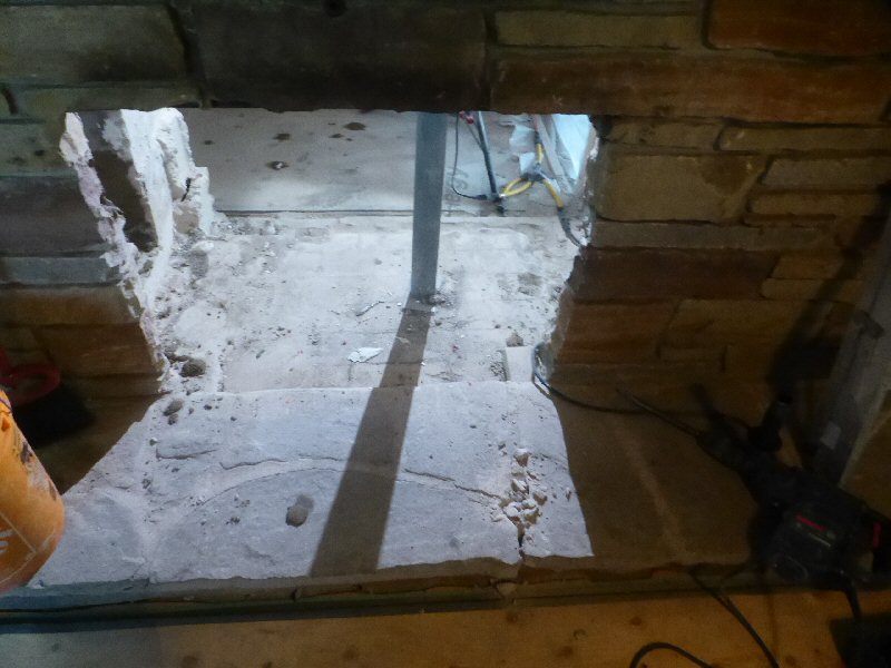
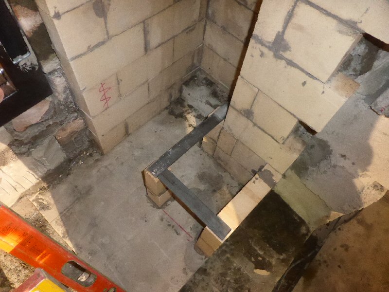
Trenching out an ashbox/air supply duct.
Custom heat exchanger on the right.
Standard
Heatkit heat exchange channel on the left. The Heatkit channel is
precast high density castable refractory,
and is only 1.25" thick. This will provide good heat transfer to the surrounding air space.
Once the glass reinforcing on the back of the stone has set, the original fireplace lintel is removed.
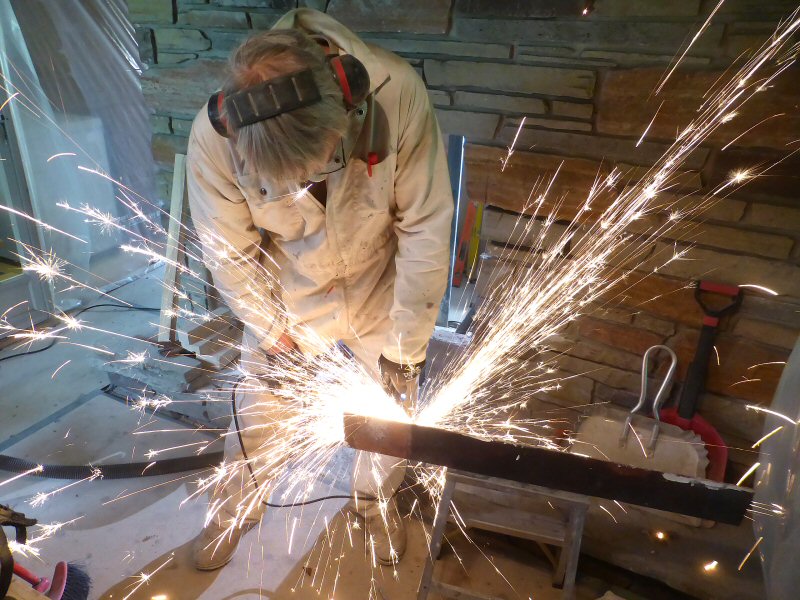
Shortening the existing steel lintel for re-use in the masonry heater opening.
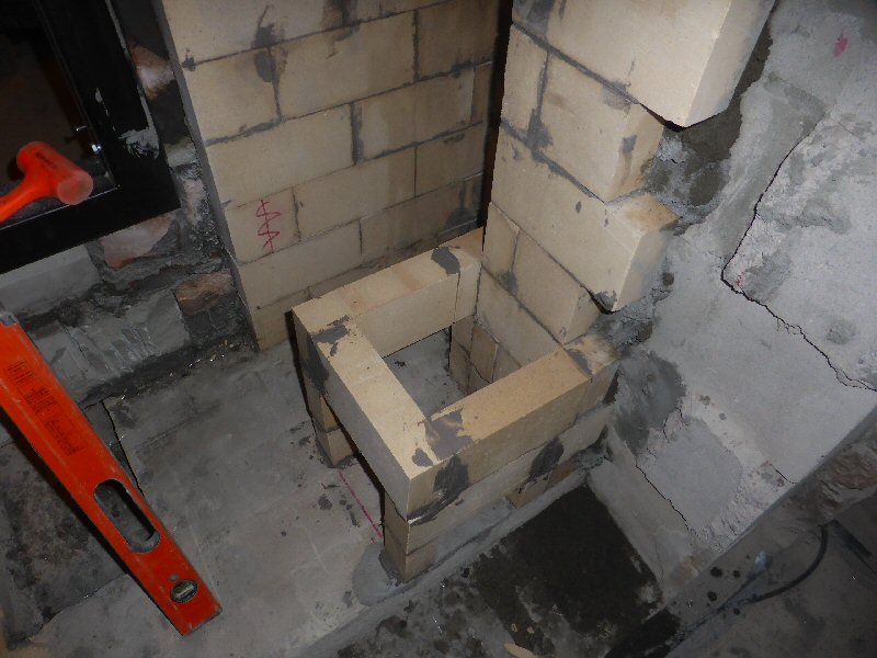
Trial fit for a Pisla ash pan
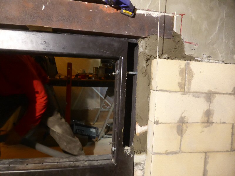
The fireplace opening has been extended on the right, to accommodate the new position of the firebox.
Stone was sawn in place with a 15 amp 9" Makita dry blade. A shop vac with HEPA filter caught about 90% of the dust.
Note the new stone below the red one near the top.
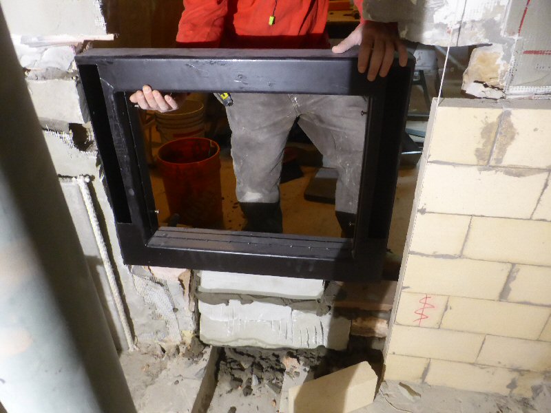
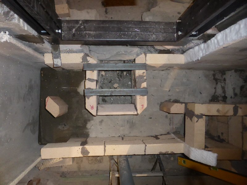
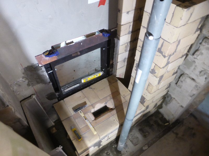
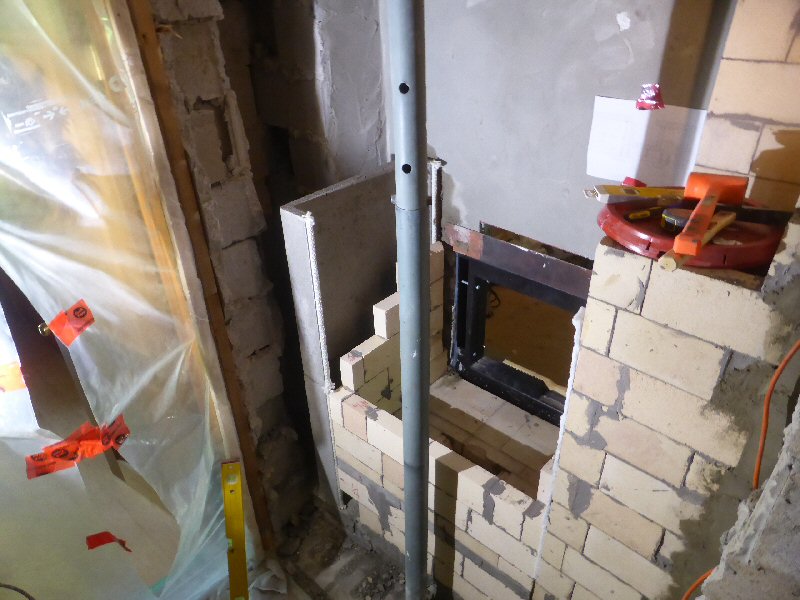
Trial fitting the air frame for the Austrian Eco-labelled firebox design.
Air enters at the bottom of the lower 3" x 4" steel tube.
Note the vertical outlets on each upright tube, to feed the Austrian air system.
Air inlet at the bottom of the air frame.
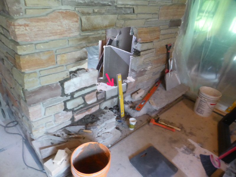
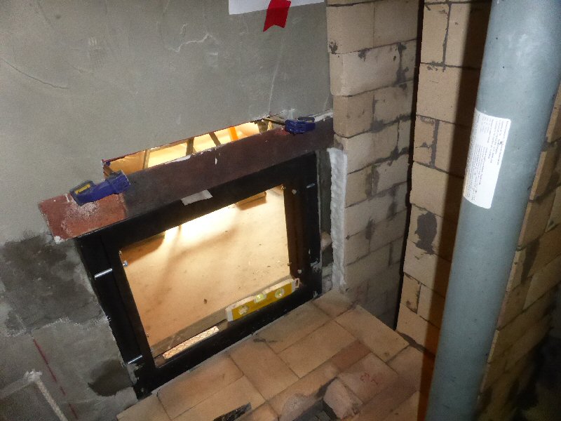
Rebuilding the opening.
Note the thinning of the stone at the arrow, to allow for an air feed to the air frame.
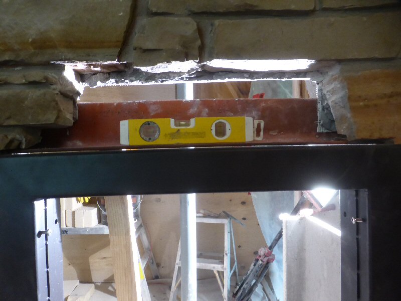
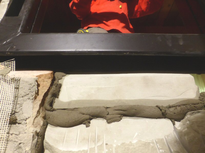
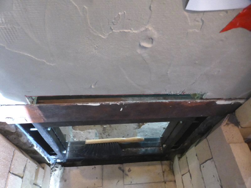
Lintel is positioned 1/8" above air frame.
Note that the air frame does not have a facing flange, and that this makes for an easy fit into the existing stone.
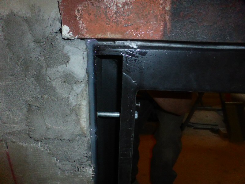
Lintel held in position by temporary clamps.
Adjusting the air frame for final fit.
Beefing up support for the lintel.
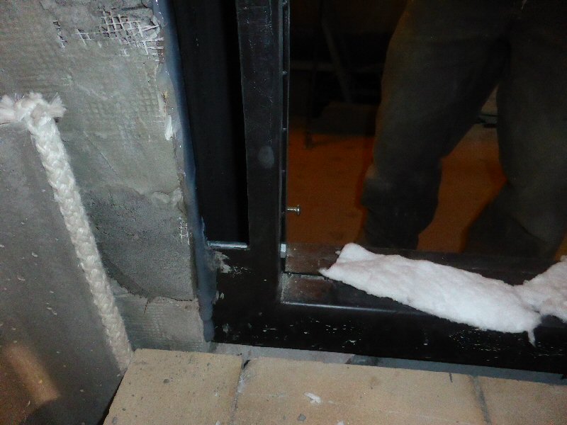
Fiberlass mat is used to create a slip joint between the upper portion of the heat exchanger and the facing.
The gap between the heat exchanger and the slip joint is slushed solid with mortar for better heat transfer.
The
core grows in height inside the facing. The growth is cumulative
towards the top, and the slip joint is not needed at the bottom.
Two outlet connections and a cleanout connection to the updrafting exit channel that will connect to the ss liner.
New Heatkit bottom end layout.
Precast firebox floor slabs.
Slabs are topped with firebrick, to create the firebox floor.
The
opening at the rear is the original rear grate opening on the Heatkit.
In this case, it provides the option of having an ash drop
opening in the hearth, or even reverting to a grate for testing purposes.
The
Austrian Eco-labelled firebox system is airtight, and does not rely on
the closing of a flue damper to stop gas flow out the chimney.
It therefore allows for the accumulation of ash and charcoal in the firebox.
On
the sides of the air frame, there is a 1/16" gap for expansion. In this
retrofit situation, the air seal can be created at the rear with
silicone. In this location it will remain below the 550F temperature limit, which was established from in-house testing
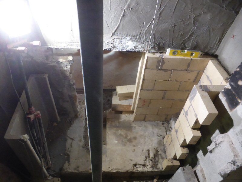
Outer wythe of firebox.
Second precast downdraft channel has been installed, and provides a corner guide for the firebricks.
Note that the bricks have been relieved where they meet the air frame, to provide an air plenum for feeding the firebox.
Inner
layer of firebox. Note the combustion air channels cut into the back of
the firebricks. The air enters the firebox through the
horizontal firebrick joints. To create the gaps, the firebricks are set onto 4mm firebox shims, which are in the cardboard box.
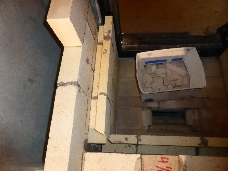
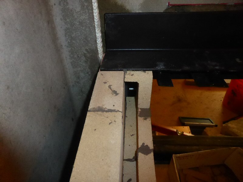
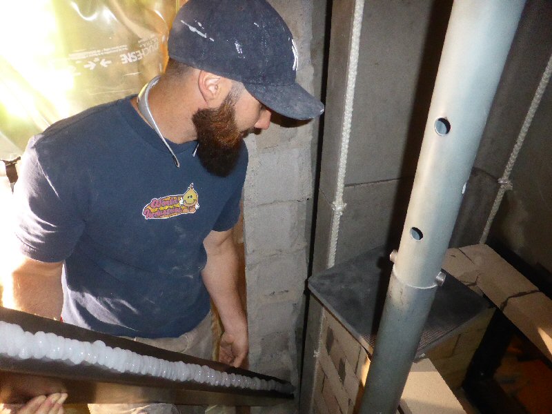
Mike is holding a strip of 4" x 4" angle, bent from 16 ga. steel.
It is siliconed to the rear of the sandstone facing, tight to the channels.
It
provides a flange against which to silicone the sheet metal
second skin to the side and rear of the core that are inside the plenum.
It also acts as a support for the side channels.
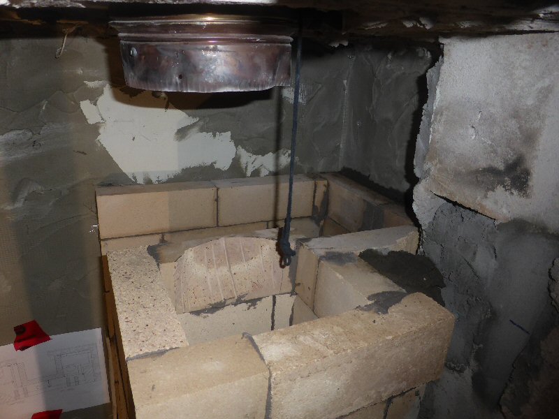
Top of the updraft channel is cut to mate with the liner.
Precast refractory castable ceiling slab is installed.
The liner will get grouted in with castable, and a castable adapter will be formed in place on top of the slab.
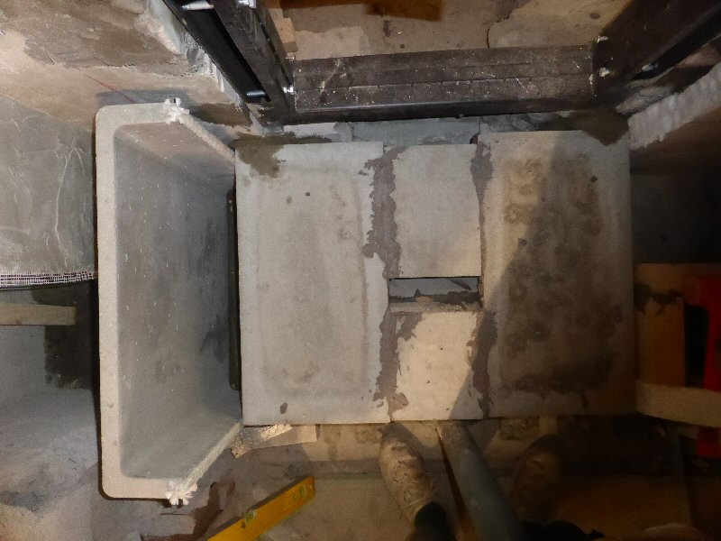
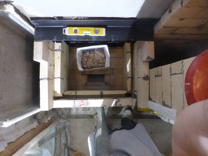
Removing a stone for the bake oven opening.
Heatkit white bake oven has a 13.5" x 27" heated floor.
The precast reinforced floor slab itself is 32.5" wide.
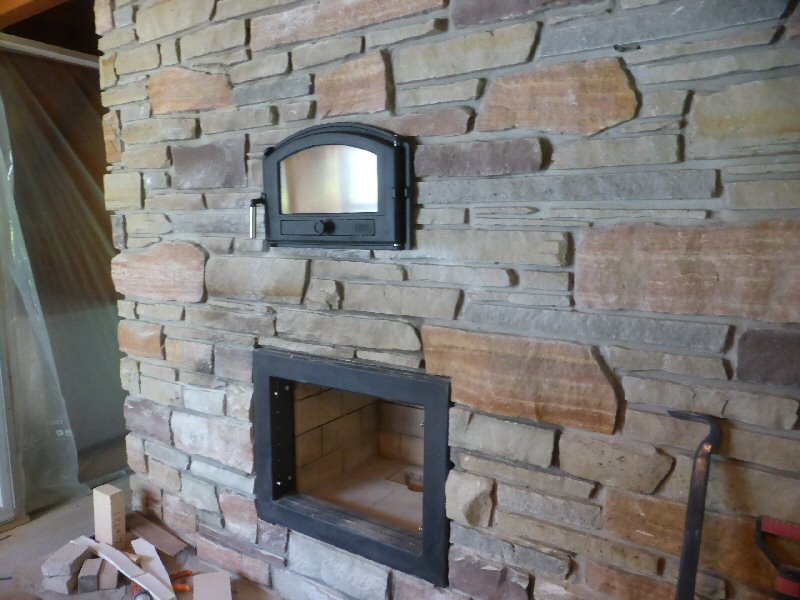
Bake oven door installed.
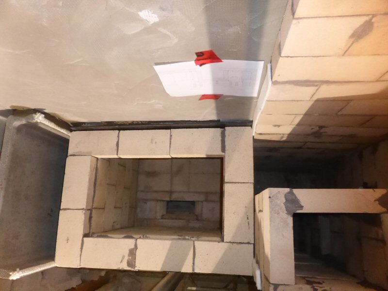
Front ceiling transition installed.
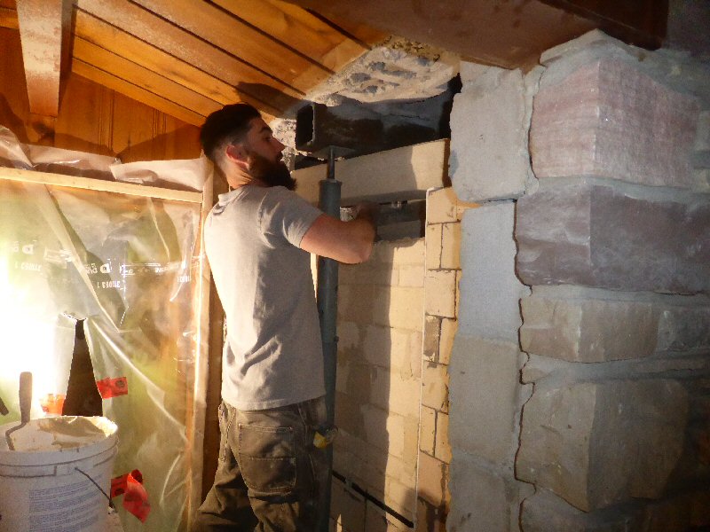
Installing the rear ceiling transition.
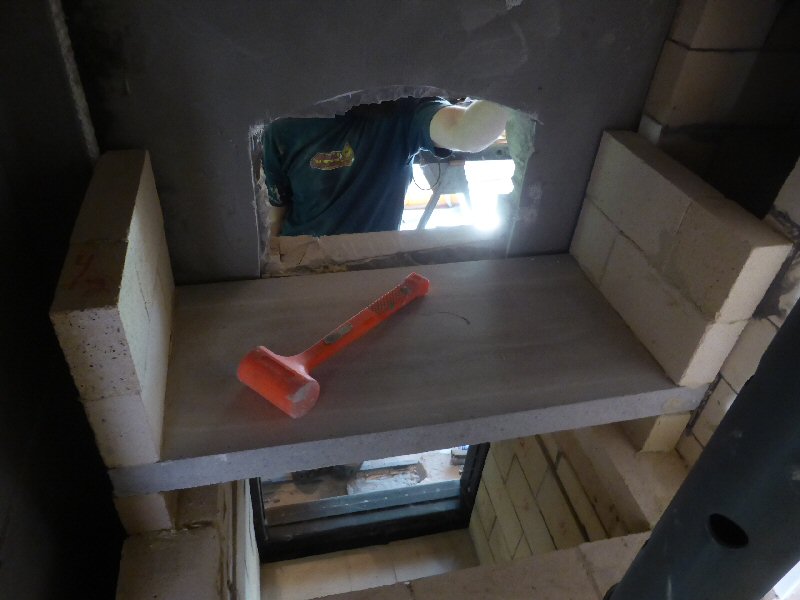
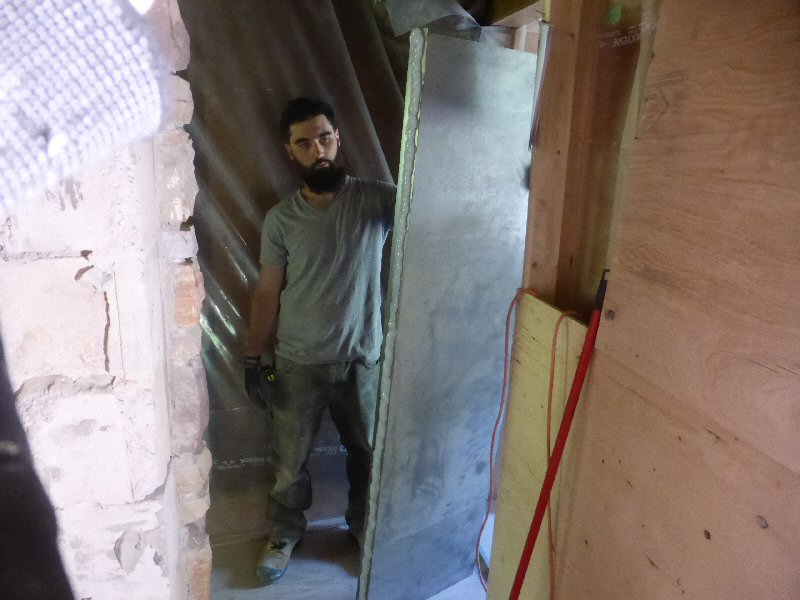
My nephew Mike looks serious as he gets ready to lift the final ceiling slab into place.
Note the slit in the plastic behind. Because the room is depressurized with a high capacity exhaust fan, this slit becomes
a fresh air inlet, ideally positioned relative to the work area.
There is a similar slit on the other side of the fireplace.
Red Tyvek tape is used to make adjustments to the slits, depending on where we are working. We were able to create
a nicely ventilated work environment, and prevent escape of any fine dust to the rest of the house, which was occupied.
An ounce of prevention is worth a pound of cure.
The vertical expansion joints are sealed with silicone.
The sheet metal for the side. Note the heavy bead of GE Type I Clear silicone on the 4" flange,
which will mate with the flange installed earlier.
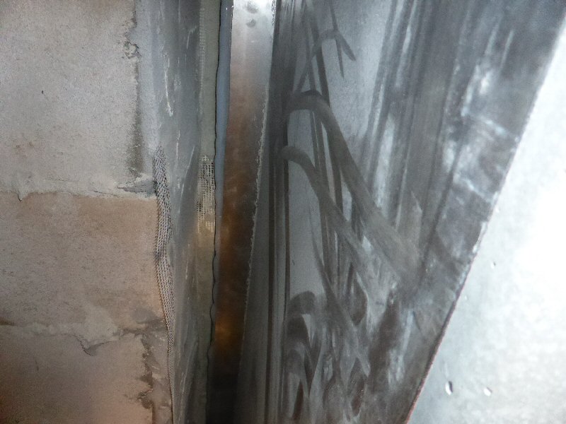
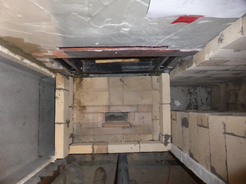
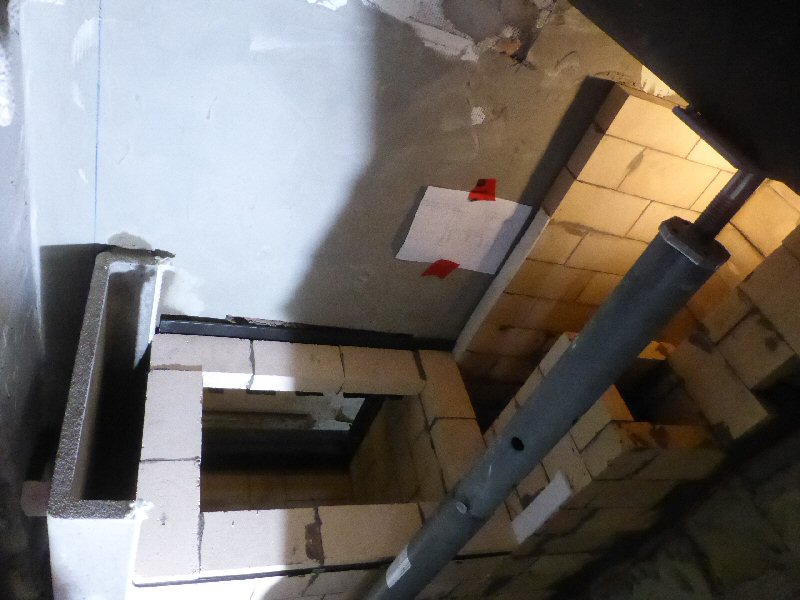
A view inside the cavity, looking towards the front facing.
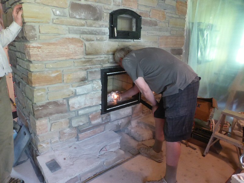
Mike had to leave for another job, so just enough time to light a test fire.
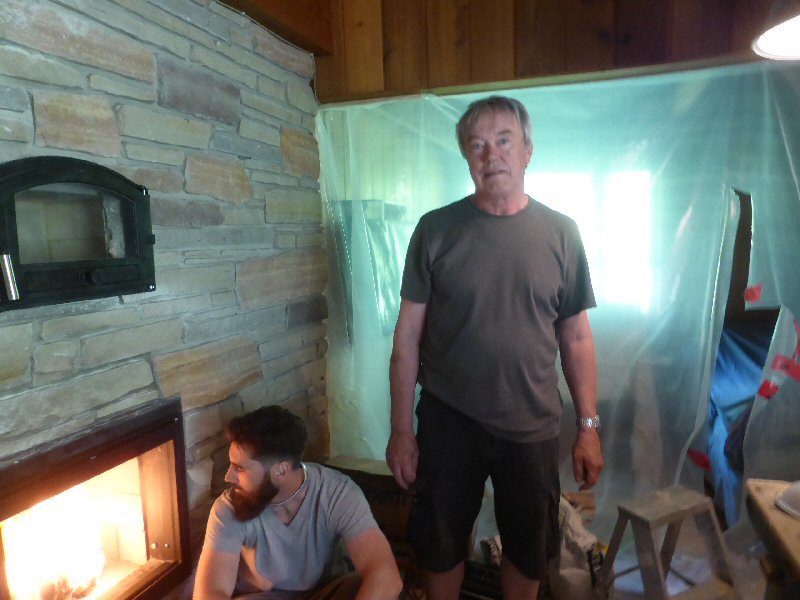
Checking it out.
In order to install the rear sheet metal, the jack post had to be temporarily removed and the support transferred onto
the rear wall of the core.
When loosening and tightening the jack post, there was no hint whatsoever of any give in the masonry.
The structural steel system was added for redundancy.
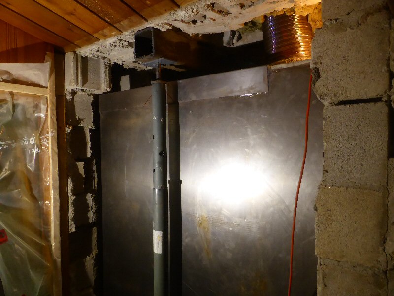
Rear skin in place. Top skin is in place also, note the 4" angle piece that makes the connection and provides the seal between
the rear and top.
Closing in the back. 4" CMU, glued with rapid thinset.
4" blocks are skinned over with glass and thinset. This provides a tensile skin, and much more flexural strength than just
concrete blocks. It also ties the new block to the old corner without requiring toothing and careful grouting.
Ready for many years of enjoyment.
This page last updated on March 28, 2023
This page created on June 5, 2014
Back to: